12 Results
View results:
Sort by:

The goal of using the RFEM 6 and Blender with the Bullet Constraints Builder add-on is to obtain a graphical representation of the collapse of a model based on real data of physical properties. RFEM 6 serves as the source of geometry and data for the simulation. This is another example of why it is important to maintain our programs as so-called BIM Open, in order to achieve collaboration across software domains.

Consideration of p-δ Second-Order Effects in RFEM 6 and RSTAB 9

Describing the procedure for the serviceability limit state design of a floor slab made of steel fiber reinforced concrete. This article shows how to perform the corresponding design for the SLS by means of the iteratively determined FEA results.

Steel-fiber-reinforced concrete is mainly used nowadays for industrial floors or hall floors, foundation plates with low loads, basement walls, and basement floors. Since the publication in 2010 of the first guideline about steel-fiber-reinforced concrete by the German Committee for Reinforced Concrete (DAfStb), a structural engineer can use standards for the design of the steel fiber-reinforced concrete composite material, which makes the use of fiber-reinforced concrete increasingly popular in construction. This article describes the nonlinear calculation of a foundation plate made of steel fiber-reinforced concrete in the ultimate limit state with the FEA software RFEM.

Determining the Material Properties of Steel-Fiber-Reinforced Concrete and Their Application in RFEM
Steel-fiber-reinforced concrete is mainly used nowadays for industrial floors or hall floors, foundation plates with low loads, basement walls, and basement floors. Since the publication in 2010 of the first guideline about steel-fiber-reinforced concrete by the German Committee for Reinforced Concrete (DAfStb), a structural engineer can use standards for the design of the steel fiber-reinforced concrete composite material, which makes the use of fiber-reinforced concrete increasingly popular in construction. This article explains the individual material parameters of steel-fiber-reinforced concrete and how to deal with these material parameters in the FEM program RFEM.

When modeling a reinforced concrete rib with a masonry wall above, there is the risk that the rib is underdesigned if the structural behavior of the masonry is not correctly considered and the connection between the masonry wall and downstand beam is not modeled sufficiently accurately. This article deals with this issue and shows the possible modeling options of such a structure. In this example, the reinforcement is determined only from the internal forces and without secondary minimum reinforcement.

Different methods are available for calculating the deformation in the cracked state. RFEM provides an analytical method according to DIN EN 1992-1-1 7.4.3 and a physical-nonlinear analysis. Both methods have different features and can be more or less suitable depending on the circumstances. This article will give an overview of the two calculation methods.
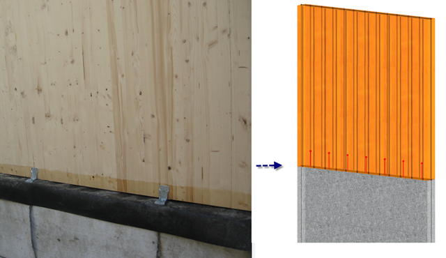
This article deals with considering end releases between surfaces with line hinges and line releases. End releases between surfaces are taken into account using line releases as well as line hinges. The examples are joints in reinforced concrete structures and frame joints in cross-laminated timber structures.
When designing reinforced concrete components according to EN 1992‑1‑1 [1], nonlinear methods of determining internal forces for the ultimate and serviceability limit states are possible. In this case, the internal forces and deformations are determined with respect to their nonlinear behaviour. The analysis of stresses and strains in cracked state usually provides the deflections, which clearly exceed the linearly determined values.
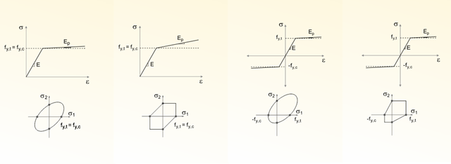
One of my earlier articles described the Isotropic Nonlinear Elastic material model. However, many materials do not have purely symmetrical nonlinear material behavior. In this regard, the yield laws according to von Mises, Drucker-Prager and Mohr-Coulomb mentioned in this previous article are also limited to the yield surface in the principal stress space.